Description
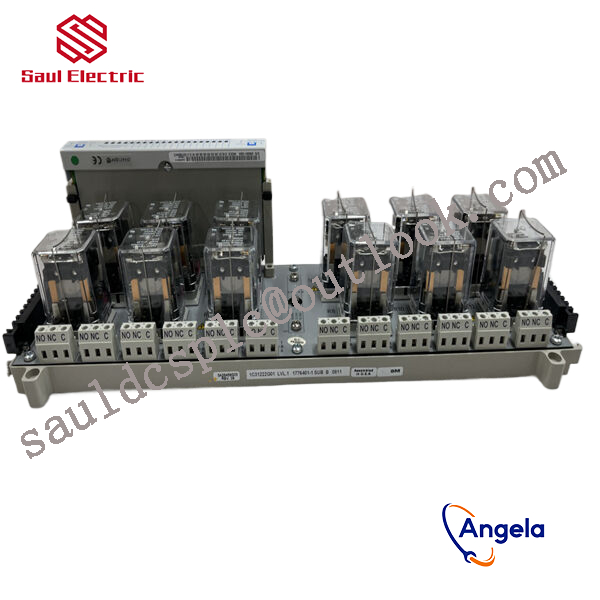
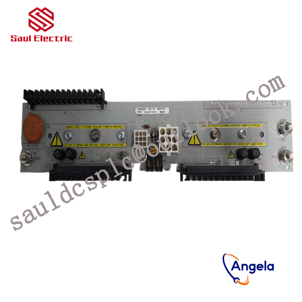
1X00781H01 New Emerson Ovation DCS Card
thereby controlling external devices or circuits.

3. Hardware circuit implementation of driver testing system
The testing system mainly includes a measurement and control platform with a computer as the core, as well as a testing platform for installing test drivers, analog loads, specialized measuring instruments, and other equipment. The circuit design adopts pulse diagnosis anti-interference and redundancy design to ensure accurate and reliable hardware design. The specific connection diagram is as follows:
Figure 2: Connection diagram of drive testing system
3.1 Startup Circuit
The startup circuit provides working voltage for the tested driver, and three current limiting resistors are connected in series to prevent surge current. At the same time, contactors, thermal relays, and filters ensure stable and reliable voltage quality. During the power on process, simply control the computer to issue a power on command, activate the contactor, complete the power on process, and achieve a safe and reliable “soft start”. The schematic diagram of the startup circuit is shown below.
responsible for processing signals from on-site sensors or driving actuator actions. For example, they may need to cooperate with devices such
as BANNER travel switch T30UIPB to receive their transmitted position signals; Or by controlling components such as Burkert solenoid valve 00131421, the on/off of fluid media can be precisely managed.
these modules integrate more complex logic processing capabilities. The core task of a pressure switch is to detect whether the pressure
has reached a preset threshold and output a switch signal. Its function is highly specific and fixed. And modules 1X00781H01 and 1
C31219G01 have the ability to comprehensively judge multiple such switch signals and transmitter signals (such as transmitter 1066-P-HT-60),
and output complex control instructions according to internal logic.