Description
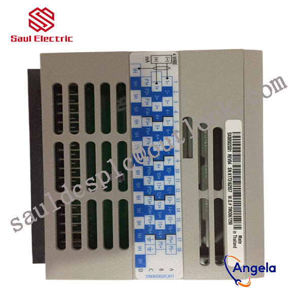
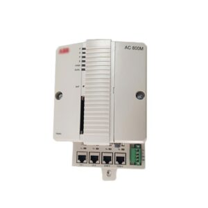
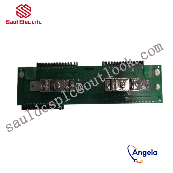
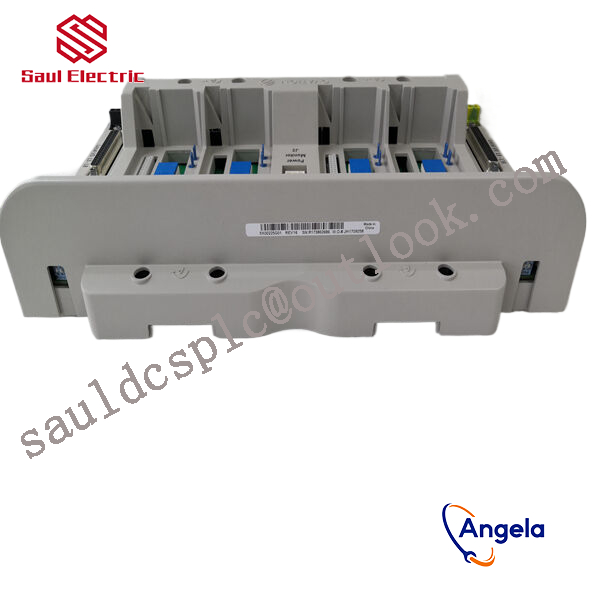
1D54561G02 Emerson Ovation Electromagnetic Output
thereby controlling external devices or circuits.
A stepper motor driver is an actuator that can convert the electrical pulse signal it receives into angular displacement. When the stepper motor driver receives an electrical pulse signal, it drives its stepper motor to rotate a fixed angular displacement (we call it the “step angle”) according to the originally set direction. Its rotation is carried out step by step at a fixed angle. We can control the displacement of its angle by controlling the number of pulses it sends, in order to achieve precise positioning; At the same time, we can also control the speed and acceleration of the stepper motor by controlling the frequency of its pulse signal, thereby achieving its speed regulation and positioning goals. Widely used in various carving machines, crystal grinding machines, medium-sized CNC machine tools, EEG embroidery machines, packaging machinery, fountains, dispensing machines, cutting and feeding systems, and other large and medium-sized CNC equipment with high resolution requirements.
The number of phases of a stepper motor refers to the number of coil groups inside the stepper motor. Commonly used stepper motors include two-phase, three-phase, four phase, and five phase. The step angle of a regular two-phase stepper motor varies depending on the number of phases, with a step angle of 1.8 degrees for a three-phase motor, 1.2 degrees for a three-phase motor, and 0.72 degrees for a five phase motor. When there is no stepper motor subdivision driver configured, users mainly rely on selecting stepper motors with different numbers of phases to meet the requirements of step angle. If a subdivision driver is used, the phase number will become meaningless, and users only need to change the subdivision number on the driver to modify the step angle.
After the subdivision of stepper motor drivers, there will be a qualitative leap in the operational performance of the motor, but all of this is generated by the driver itself and has nothing to do with the motor and control system. When in use, the only thing that users need to pay attention to is the change of the step angle of the stepper motor, which will have an impact on the frequency of the step signal sent by the control system. As the step angle of the stepper motor will decrease after subdivision, the frequency of the requested step signal should be correspondingly increased. Taking a 1.8 degree stepper motor as an example: the step angle of the driver is 0.9 degrees in half step state, and 0.18 degrees in ten step state. Therefore, under the condition of requesting the same motor speed, the frequency of the step signal sent by the control system is 5 times that of half step operation in ten step state.
The accuracy of a regular stepper motor is 3-5% of the step angle. The deviation of a single step in a stepper motor does not affect the accuracy of the next step, so the accuracy of the stepper motor does not accumulate.
responsible for processing signals from on-site sensors or driving actuator actions. For example, they may need to cooperate with devices such
as BANNER travel switch T30UIPB to receive their transmitted position signals; Or by controlling components such as Burkert solenoid valve 00131421, the on/off of fluid media can be precisely managed.
these modules integrate more complex logic processing capabilities. The core task of a pressure switch is to detect whether the pressure
has reached a preset threshold and output a switch signal. Its function is highly specific and fixed. And modules 1D54561G02 and 1
C31219G01 have the ability to comprehensively judge multiple such switch signals and transmitter signals (such as transmitter 1066-P-HT-60),
and output complex control instructions according to internal logic.