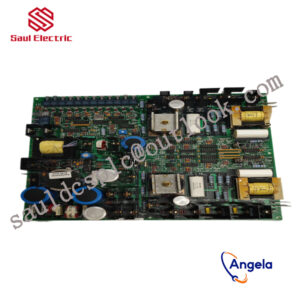
Description
IS200ESYSH3A Product Introduction
The specific application scope of the product
will depend on the needs of system integration and industrial application, but generally speaking, this type of embedded controller module can be applied to the following categories:
manufacturing processes, etc.
monitoring and control system.
of the controller module, as well as the specific needs of the customer.
designed to manage gas or steam turbines.
It has a CIMPLICITY graphical interface and an HMI with software suitable for running heavy-duty turbines.
be installed at the bottom of the cabinet. For a small setup that is easy to serve a triple redundant system, up to three components can be installed side by side.
he board can operate within a temperature range of 0 to 65 degrees Celsius without the need for a fan for cooling. NFPA Class 1. This board can be used for two applications.
Practical application of ABB industrial information control system 800xA in main shaft hoist controlintroductionThe mine hoist is an important transportation equipment for mining enterprises. Its main function is to transport the ore, personnel or equipment that need to be transported to the destination by the lifting container. Therefore, it plays a very important role in the mining production process. Usually the mine hoist control system consists of a driving part and a control part. The working mechanism of the driving part is: the motor unit drives the mechanical hoisting device, and the frequency converter or other types of hoisting control systems drive the motor unit: the working mechanism of the control part is: Each component of the hoist is coordinated and controlled by the Distributed Control System (DCS). In addition to completing basic process control, it can also integrate intelligent instruments, intelligent transmission and motor control, and even production management and safety systems into one operation and engineering environment. middle. Therefore, the mine hoist requires a control system with high performance, high reliability, and high integration.1ABB800xA system and AC800M controller introduction1.1ABB800xA system introductionThe 800xA system is an industrial information control system launched by ABB. The core of its architecture is object-oriented (ObjectOriented) technology. Due to the adoption of ABB”s unique Aspect0object concept, enterprise-level information access, object navigation and access can become standardized and simple.In order to provide a unified information platform for enterprise managers and technical personnel, the 800xA system provides a base platform (BasePlatform), which relatively separates the process control part and production control management and organically combines them together. As shown in Figure 1, the middle part is the basic platform, the upper part is the production control management part, and the lower part is the process control part. The basic platform provides standard interfaces for these two parts for data exchange.1.2 Introduction to ABBAC800M controller and its programming configuration toolsAC800M controller is ABB”s latest controller series, which includes a series of processors from PM851 to PM865. The AC800M controller itself has a pair of redundant TCP/IP interfaces. It can use the MMs protocol to communicate with other control devices and 800xA operator stations through Ethernet. It can also use the Modbus protocol and Point-Point protocol through 2 serial ports. communication. The programming and configuration tool of AC800M is ControlBuilderM, referred to as CBM. It supports standard ladder diagram, function block language, text description language and assembly language to write control logic.2. Improve the design and implementation of control system functions2.1 Implementation of elevator operating speed curveOne of the main tasks of the lifting control system is to control the lifting motor to operate according to the speed-position curve given by the design, so that the lifting container passes through the acceleration section, the uniform speed section and the deceleration section successively, and stops accurately after completing the specified lifting distance. somewhere in the wellbore. In order to realize the function of precise position calculation, the designed elevator control system must be able to perform high-precision position calculation based on the photoelectric encoder connected to the main shaft of the elevator drum. The calculation formula is as follows:In the formula, s is the actual position value of the elevator: sp is the distance corresponding to two consecutive encoder pulses: AN is the difference between the encoder count value at the reference position and the current position (signed variable): s0 is the reference position value.The encoder counts are distributed according to the circumference of the drum. After the number of pulses Np generated by the encoder rotation is known, the diameter of the circumference of the centerline of the wire rope wrapped around the drum must be accurately known, so that it can be calculated according to formula (2) The distance sp corresponding to the two encoder pulses:In the formula, D is the circumferential diameter of the centerline of the wire rope: Np is the number of pulses for one revolution of the known encoder.But in formula (2), there is a value D that keeps getting smaller as the system runs. This is because the wire rope used in the elevator is wrapped around the drum, and there is a lining between the wire rope and the drum that increases friction. This liner will become thinner and thinner as the system continues to wear and tear, causing the diameter of the circle formed by the center line of the steel wire rope to gradually become smaller. When the pad wears to a certain extent, it will cause a large position calculation error. In order to solve the above problems, the two parking position switches in the shaft are used to correct the drum diameter, because the distance between the two parking positions can be obtained through actual measurement with high accuracy. During the actual operation, record the encoder count values at the two parking positions respectively. According to formula (3), the actual correction value of sp can be calculated:In the formula, sd is the distance between two parking positions: Abs is the absolute value operation: N is the encoder count value when there are two parking positions.In this way, the initial sp value is first set according to the given design parameter value, and then the value is corrected according to the actual operating conditions, which can effectively ensure the accuracy of position calculation. At the same time, sp” can also be substituted into formula (2), and the D value can be obtained in turn, which can be used as a basis for judging whether the liner is seriously worn.After obtaining the elevator position value, the speed control curve can be calculated according to formula (4):
IS215VCMIH2B I/O excitation redundant module GE
DS200SDCIG1AEB Processor/Controller Mark VI System
IS230TNTRH1C High performance processor module GE
IS220PPDAH1A Processor/Controller Mark VI System
IS220PRTDH1B GE power control board
IS400JPDHG1ABB From General Electric in the United States
IS200TPROS1CBB Processor/Controller Mark VI System
IS210AEDBH3A From General Electric in the United States
IS200TRLYH1B Processor/Controller Mark VI System
DS200VPBLG1AEE High performance processor module GE
IS200DSPXH2CAA From General Electric in the United States
IS200ERSCG2A High performance processor module GE
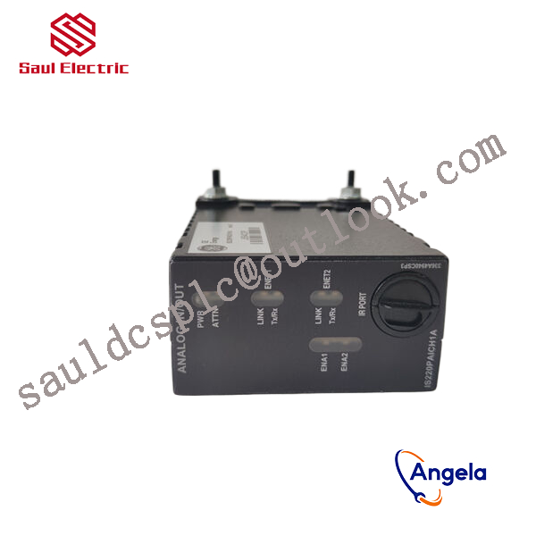
IS220PAOCH1A I/O excitation redundant module GE
DS200TCQAG1BHF From General Electric in the United States
IS220YSILS1BB From General Electric in the United States
IS200DTAIH1ACC Gas turbine system Mark VI
DS3820PSCB1C1B I/O excitation redundant module GE
IS420UCSBH1A Processor/Controller Mark VI System
IS220PAICH1B I/O excitation redundant module GE
IS210DPWAG1AA From General Electric in the United States
DS200DMCBG1A Processor/Controller Mark VI System
IS220PDIOH1A I/O excitation redundant module GE
IS220PSCAH1A High performance processor module GE
IS200GDDDG1A From General Electric in the United States
IS220YDIAS1A Gas turbine system Mark VI
IS200SRLYH2AAA GE power control board
IS215UCVEM06A Gas turbine system Mark VI
IS420UCSBH1A I/O excitation redundant module GE
IS210TRPGH1B Processor/Controller Mark VI System
DS200TCCBG8BED Processor/Controller Mark VI System
IS215ACLEH1B From General Electric in the United States
IS200TRESH1A From General Electric in the United States
IS215UCCAM03 Processor/Controller Mark VI System
DS200SLCCG3ACC Processor/Controller Mark VI System
DS200TCQCG1BHF Processor/Controller Mark VI System
IS200TSVCH1AJE High performance processor module GE
IS200ISBDG1AAA GE power control board
IS200VAICH1D High performance processor module GE
IS220PPDAH1A GE power control board
IS220PAOCH1BD GE power control board
IS230SAISH1A High performance processor module GE
IS215ACLEH1B Gas turbine system Mark VI
IS200VATFG1AAA I/O excitation redundant module GE
IS220PRTDH1A From General Electric in the United States
IS200TTURH1B High performance processor module GE
IS200TGENH1A Processor/Controller Mark VI System
IS220PAICHIA I/O excitation redundant module GE
IS200EISBH1AAA High performance processor module GE
IS2020RKPSG3A Processor/Controller Mark VI System
IS200VAICH1DAB GE power control board
IS420ESWBH3A Gas turbine system Mark VI
DS200PLIBG1ACA GE power control board
IS400TCASH1AEC I/O excitation redundant module GE
IS200TNH1A Processor/Controller Mark VI System
IS220PDIOH1B I/O excitation redundant module GE
IS210DTTCH1AA GE power control board
DS200CPCAG1A Processor/Controller Mark VI System
DS200SDCCG5AHD I/O excitation redundant module GE
IS215VCMIH1B Gas turbine system Mark VI