Description
I. Brand Background
II. Product Features
- High Performance: The 8LSA75R0015D7070 servo motor offers high precision, rapid response, and excellent stability, meeting the demands of various complex automation applications.
- Integrated Safety Technology: B&R”s servo motors incorporate advanced safety technologies, such as the openSAFETY standard,
- ensuring the safety of operators while supporting machine functionality. This safety technology adapts to changing configurations and operates reliably worldwide.
- Easy Management: With intelligent safety response capabilities, the 8LSA75R0015D7070 servo motor simplifies machine option management without compromising safety levels.
- This helps reduce downtime risks and enhance production efficiency.
- Networked Collaboration: B&R”s integrated, networked safety technology enables coordinated responses to safety events across the entire production line.
- The use of safety standards like openSAFETY ensures secure communication and interoperability between devices from different manufacturers.
- Powerful Software Support: B&R”s Automation Studio software development platform provides robust support for configuring, commissioning,
- and maintaining servo motors. Users can easily accomplish various automation tasks through this platform.
III. Application Areas
IV. Product Advantages
- Genuine Products: The 8LSA75R0015D7070 servo motor is manufactured in Austria, ensuring product quality and performance.
- Professional Services: B&R has a professional technical support and after-sales service team capable of providing timely and efficient technical support and solutions to users.
- Customization Options: B&R offers customized servo motor solutions to meet the specific needs of different users.
The ordinary motors, stepper motors, servo motors, and servos referred to here refer to DC micro motors, and we often come into contact with DC motors. Electric motor,
also known as “motor”, refers to an electromagnetic induction device that maintains the transformation or transmission of electromagnetic energy according to the
law of electromagnetic induction. Motor, also known as (alias motor), is expressed in the power circuit using the English letter “M” (formerly known as “D”). Its main function is
to generate driving torque, which is used as a power source for electrical appliances or various machines. The generator is represented by the letter “G” in the circuit.
wKgaoma8UPOAGBo0AAPxhsAzJTw322.png
General-purpose motor
Ordinary motors are commonly seen in electric toys, razors, etc. They are usually DC brushed motors. This type of motor has the characteristics of high speed and low torque.
Generally, it only has two pins. When the positive and negative poles of the battery are connected to the two pins, it will start rotating. Then, when the positive and negative poles
of the battery are connected to the two pins in opposite directions, the motor will rotate in the opposite direction.
gear motor
A deceleration motor is a combination of an ordinary motor and a gearbox, which reduces the speed and increases the torque, making the ordinary motor more widely applicable.
stepper motor
A stepper motor is an open-loop control element that converts electrical pulse signals into angular displacement or linear displacement. In non overloaded situations, the speed and stopping position
of the motor depend only on the frequency and number of pulses of the pulse signal, and are not affected by load changes. When the stepper driver receives a pulse signal
, it drives the stepper motor to rotate a fixed angle in the set direction, called the “step angle”, and its rotation runs step by step at a fixed angle. By controlling the number of pulses, the angular
displacement can be controlled to achieve accurate positioning; At the same time, the speed and acceleration of the motor can be controlled by controlling the pulse frequency, thus achieving the purpose of speed regulation.
servo
The servo motor is mainly composed of a casing, a circuit board, a coreless motor, gears, and a position detector. Its working principle is that the receiver sends a signal to the servo
, which is then determined by the IC on the circuit board to determine the direction of rotation. The coreless motor is then driven to start rotating, and the power is transmitted to the swing
arm through the reduction gear. At the same time, the position detector sends back a signal to determine whether the positioning has been reached. The position detector is actually
a variable resistor, and the resistance value changes when the servo rotates. By detecting the resistance value, the angle of rotation can be determined.
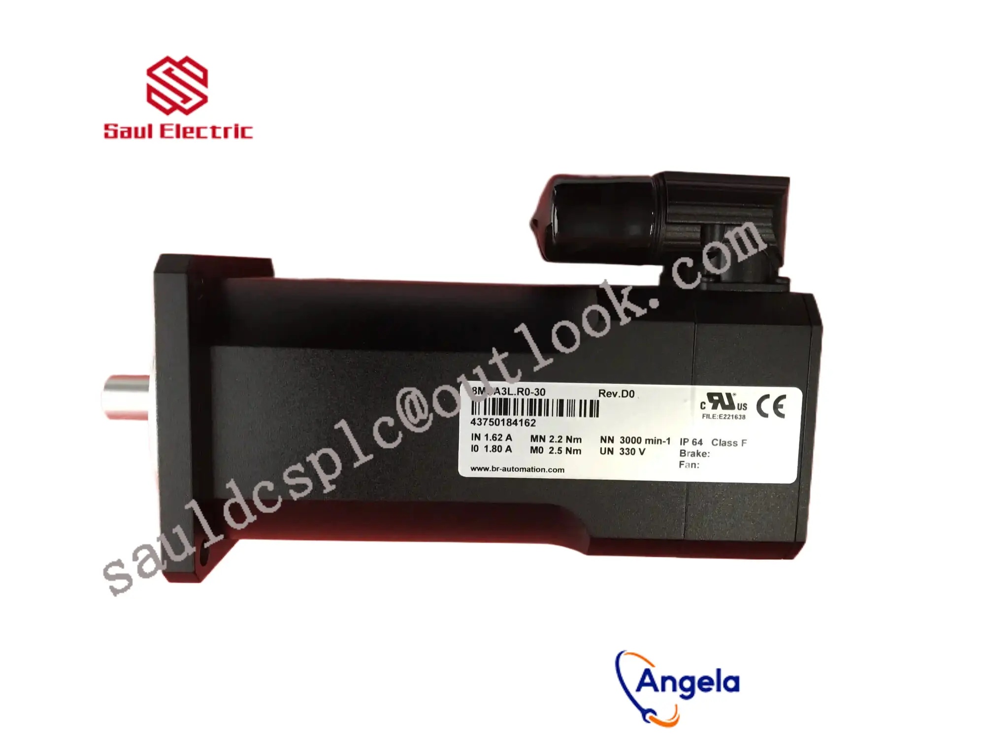
The specifications provided by servo motor manufacturers usually include basic information such as external dimensions (mm), torque (kg/cm), speed (seconds/60 °), test voltage (V), and weight (g).
The unit of torque is kg/cm, which means that at a length of 1 cm on the swing arm, it can lift several kilograms of weight. This is the concept of a lever
arm, therefore the longer the length of the swing arm, the smaller the torque. The unit of speed is sec/60 °, which means the time required for the servo to rotate 60 °.
servo motor
Servo motor, also known as actuator motor, is used as an actuator in automatic control systems to convert received electrical signals into angular displacement or angular velocity output
on the motor shaft. It is divided into two categories: DC and AC servo motors. Its main feature is that when the signal voltage is zero, there is no self rotation phenomenon, and the speed decreases uniformly with the increase of torque.
Servo motors mainly rely on pulses for positioning. Basically, it can be understood as follows: when a servo motor receives one pulse, it will rotate the corresponding angle of one pulse to
achieve displacement. Because servo motors themselves have the function of emitting pulses, every time they rotate an angle, they will emit a corresponding number of pulses. This forms a
response or closed loop with the pulses received by the servo motor. In this way, the system will know how many pulses have been sent to the servo motor and how many pulses have
been received back. In this way, the rotation of the motor can be accurately controlled to achieve precise positioning, which can reach 0.001mm.
Servo motors are divided into two categories: AC servo and DC servo.
AC servo motors are divided into two types: asynchronous AC servo motors and synchronous AC servo motors.
DC servo motors are divided into brushed and brushless motors. Brushed motors have low cost, simple structure, large starting torque, wide speed range, easy control, and require maintenance. However,
maintenance is inconvenient (such as replacing carbon brushes) and generates electromagnetic interference, which has environmental requirements. Therefore, it can be used in cost sensitive general industrial and civilian applications.
Principle of Reduction Motor
Gear reduction motor, also known as gear reduction motor or reduction motor, is a closed transmission gear reduction device driven by a motor. It is a reduction transmission mechanism that integrates the
motor and gearbox to reduce speed and increase torque, in order to meet the needs of mechanical equipment operation.
The purpose of a reduction gear motor is to reduce the speed.
The required speed of the motor is achieved through a reduction gearbox, commonly known as the output speed. ② Increase torque.
Under the same power conditions, the slower the output speed of the gear reduction motor, the greater the torque, and vice versa. ③ Change the transmission direction.
For example, we can use two sector gears to vertically transmit force to another axis of rotation. ④ Clutch function.
We can achieve the goal of instant braking when power is cut off by installing a brake clutch.
Basic principle of stepper motor
Working Principle:
Usually, the rotor of a motor is a permanent magnet, and when current flows through the stator winding, a vector magnetic field is generated by the stator winding.
The magnetic field will drive the rotor to rotate by an angle,
so that the direction of the rotor”s pair of magnetic fields is consistent with that of the stator”s magnetic field. When the vector magnetic field of the stator rotates by an angle.
The rotor also rotates an angle with the magnetic field. For every input of an electrical pulse, the motor rotates one angle and advances one step.
The angular displacement output is proportional to the number of pulses input, and the rotational speed is proportional to the pulse frequency.
Changing the order of winding electrification will cause the motor to reverse. So the rotation of the stepper motor can be controlled by controlling the number and frequency of pulses,
as well as the sequence of energizing each phase winding of the motor.
Heating principle:
Various types of motors commonly seen have iron cores and winding coils inside. The winding has resistance, and when energized, it will produce losses.
The magnitude of the losses is proportional to the square of the resistance and current, which is commonly known as copper losses.
If the current is not a standard DC or sine wave, harmonic losses will also occur; The iron core has hysteresis eddy current effect, which can also cause losses in alternating magnetic fields.
The magnitude of these losses is related to the material, current, frequency, and voltage, which is called iron loss. Copper and iron losses will both manifest in the form of heat, thereby affecting the efficiency of the motor. Stepper motors generally pursue positioning accuracy and torque output, with relatively low efficiency, large current, and high harmonic components. The frequency of current alternation also varies with the speed, so stepper motors generally have heating problems, which are more severe than general AC motors.
Principle of servo motor
The PWM wave enters the internal circuit to generate a bias voltage, triggering the motor to move the potentiometer through the reduction gear. When the voltage difference is zero, the motor stops rotating, thus achieving the servo effect.
The PWM protocol for servos is the same, but the latest servos may be different
The protocol is generally: the high-level width is between 0.5ms and 2.5ms to control the servo to rotate at different angles.
Working principle of servo motor
The working principle of servo motors is relatively simple, but their operation is relatively efficient. The servo circuit is built into the motor unit and uses a flexible shaft typically equipped with gears. The electrical signal controls the motor and also determines the amount of shaft movement. The internal setup of the servo motor is simple: a small DC motor, control circuit, and potentiometer. The DC motor is connected to the control wheel through gears. When the motor rotates, the resistance of the potentiometer changes, and the control circuit can accurately adjust the motion and direction.
When the shaft is in the correct (ideal) position, the motor stops supplying power. If the shaft does not stop at the target position, the motor continues to run until it enters the correct direction. The location of the target is transmitted through a signal line using electrical pulses. So, the speed of the motor is directly proportional to the actual and ideal positions. When the motor approaches the desired position, it begins to slowly rotate, but when the motor rotates farthest, the speed is very fast. In other words, servo motors only need to complete tasks as quickly as possible, making them highly efficient devices.
Honeywell thickness gauge spare parts/Schneider Aile series servo drive LXM, BMX module, 140/TSX module/ABB DCS module, robot spare parts, IGBT module board, ABB tension sensor/Siemens Robbins series products, smoke analyzer 7MB, motor protector 3UF, wide temperature series module 6AG (recommended by project customers for delivery time), software 6FC58516FC5852/Rexroth servo drive motor/Fanuc servo drive motor/Yaskawa servo drive motor
1. Undertake the transformation, design, installation and commissioning of automation integrated systems such as PLC control cabinets, frequency conversion cabinets, medium and low voltage switchgear, etc;
2. Maintenance: servo drives, PLC modules, frequency converters, touch screens, DCS cards, etc;
3. KUKA robot maintenance and parts replacement.