Description
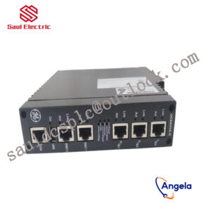
8440-2082 WOODWARD 2301A Speed Control Controller
Non differential regulation is mainly used for constant speed control and is suitable for single machine operation or multiple prime movers working together in an isolated power grid. Differential regulation provides more control flexibility.
further enhancing its performance and application range.
rich additional functions, and high-precision output signals. Whether it is in the fields of generator sets, compressors, pump stations, or ships and locomotives, it can effectively ensure the stable operation of equipment within the set range.
power measurement level 1, editable screen, multi interface toolkit connection, etc. All details can be found in Woodward easyYgen manual 37582A
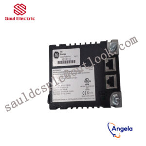
The rated operating temperature range of this model is -20 to 70 ° C; the rated temperature range of the LT model is -40 to 70 ° C, suitable for outdoor use.
8440-2082 is equipped with a monitor (not available on the 3100 model) and is designed for front panel installation.
The built-in HMI has a color LCD and soft keys (now with dedicated buttons) for direct control of the 8440-2082 device. Multi level password protection can prevent unauthorized changes.
The generator set has four operating modes and the option to configure a manual circuit breaker control device.
How to use 8440-2082?
What is 8440-2082 used for?
8440-2082 Customs Code
Design and implementation of variable frequency transmission system based on ABB hardware architectureintroductionWith the increasing development of transmission technology and the increasing demand for actual use, variable frequency transmission systems have been widely used.As a Fortune 500 company in the world, ABB is a leader in the fields of power and automation technology and has strong capabilities in control systems, high-voltage, medium-voltage and low-voltage frequency conversion technology and transmission technology. Therefore, this article mainly relies on ABB”s control, frequency conversion and transmission technology, and uses related hardware products to design and implement the frequency conversion transmission system.To truly design and implement a usable variable frequency drive system, the entire system must be fully equipped, conveniently operable and compatible with a wide range of needs, so that it can be used without changing the control method and operation. According to the actual control needs, that is, combining frequency converters with different performances and variable frequency motors with different speeds or torques to quickly build and realize a variety of control requirements.1 System design purpose and compositionThe design purpose of this system is to control ABB inverters through local and remote control methods and complete 4 independent channels of closed-loop speed control to drive different test objects to rotate.The entire control system consists of the following four main components: remote control computer, panel industrial computer (touch screen), PLC and speed-regulating frequency converter. The system design block diagram is shown in Figure 1.In order to ensure the accuracy of motor speed control, an encoder module is added. The PLC can obtain the feedback of the rotary encoder in the frequency converter through the ProfibusDP protocol. The speed control is performed through the frequency converter for internal PID closed-loop control.2 System hardware implementation2.1 Control some hardwareThe control part of the hardware mainly refers to the sum of hardware that supports operators to use the equipment directly or indirectly and complete the functions of the equipment. Its main hardware includes computer control terminal, touch screen control terminal, PLC control unit, other auxiliary circuits and measurement and control components.2.2 Transmission hardwareThe transmission hardware mainly refers to the total number of equipment that can relatively independently perform a complete transmission function. Its main hardware includes frequency converters, variable frequency motors (configured with rotary encoders as needed) and other auxiliary circuits. Among them, the selection of motors and frequency converters should be based on the principle of selecting the motor first and then selecting the frequency converter. details as follows:First, according to the tangential speed at which the object under test is to complete rotation, select the motor speed according to the following formula:Secondly, choose based on several other important basic parameters of the motor, such as system hardness, torque, weight, etc. This system uses ABB”s variable frequency motor.Finally, select an appropriate frequency converter based on the motor power. In addition, the actual situation of the object being tested must also be taken into consideration, such as whether the rotating load belongs to the heavy-load usage of the frequency converter, etc.3Software systemSystem software includes three major categories in total, namely computer control software, touch screen software and PLC software. Among them, the PLC software, as the underlying software, is responsible for the interaction with the computer control software and touch screen software on the upper side, and the interaction with the frequency converter on the lower side. Therefore, from the architecture of the entire software system, it can be defined as a host and slave computer structure.3.1 System development platformThe software system has two control methods: remote and local. The development platforms for the three major categories of software are Windows operating system, LabVIEW[4] integrated development environment, CodesysV2.3, and CP400.3.2 System software architectureThe software of the entire system is divided into three types, namely remote control software, PLC control software and local control software. Among them, the remote control software runs under the Windows operating system and is developed under the LabVIEW integrated development environment; the PLC control software is developed under the CodesysV2.3 programming environment; the local control software runs on the touch screen computer and is developed under the CP400 environment. The relationship between the three software is shown in Figure 2.
5417-176 From Woodward, USA
8915-111 Generator Parts Speed Controller 2301A Speed
8405-020 WOODWARD Speed Sensor Full Series
5464-716A WOODWARD Speed Sensor Full Series
5464-660 WOODWARD Speed Sensor Full Series
5466-250 WOODWARD Speed Sensor Full Series
5463-143 Controller debugger generator WOODWARD
5503-335 Generator Parts Speed Controller 2301A Speed
8236-144D From Woodward, USA
8239-001 Generator Parts Speed Controller 2301A Speed
9905-678 From Woodward, USA
A8523-210 Generator Parts Speed Controller 2301A Speed
5501-371 From Woodward, USA
8256-016 Generator Parts Speed Controller 2301A Speed
9907-955 Generator Parts Speed Controller 2301A Speed
5501-428 Generator Parts Speed Controller 2301A Speed
5466-1035 Generator Parts Speed Controller 2301A Speed
9907-164 Controller debugger generator WOODWARD
5501-430 From Woodward, USA
9905-002N Controller debugger generator WOODWARD
5463-431 WOODWARD 2301A Speed Control Controller
5501-381 Controller debugger generator WOODWARD
8290-191 From Woodward, USA
9907-173 Controller debugger generator WOODWARD
5448-903 WOODWARD Speed Sensor Full Series
8404-5004 Controller debugger generator WOODWARD
A9904-111 Generator Parts Speed Controller 2301A Speed
5462-896 WOODWARD Speed Sensor Full Series
5461-083 Generator Parts Speed Controller 2301A Speed
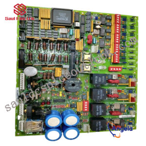
8301-633 WOODWARD generator set speed control board
G8516-052 From Woodward, USA
5403-616 From Woodward, USA
5460-842 WOODWARD Speed Sensor Full Series
8230-896 Controller debugger generator WOODWARD
5463-373 From Woodward, USA
9907-827 WOODWARD 2301A Speed Control Controller
5466-409 WOODWARD generator set speed control board