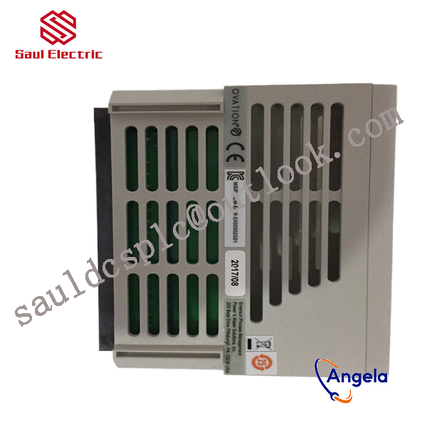
Description
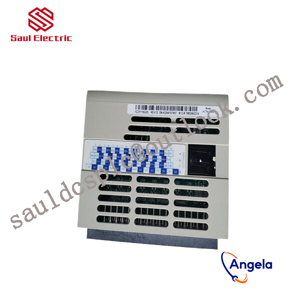
5X00502G01 New Emerson Ovation DCS Card
thereby controlling external devices or circuits.
The driving circuit of a bipolar stepper motor is shown in Figure 2, which uses eight transistors to drive two sets of phases. Bipolar drive circuits can simultaneously drive four wire or six wire stepper motors. Although four wire motors can only use bipolar drive circuits, they can significantly reduce the cost of mass-produced applications. The number of transistors in the bipolar stepper motor drive circuit is twice that of the unipolar drive circuit. The four lower transistors are usually directly driven by a microcontroller, while the upper transistors require a higher cost upper drive circuit. The transistor of a bipolar drive circuit only needs to withstand the motor voltage, so it does not require a clamping circuit like a unipolar drive circuit.
Stepper Driver Principle Stepper Motor Driver Selection
4. Microstep driver
Stepper Driver Principle Stepper Motor Driver Selection
Microstep driving technology is a current waveform control technology. The basic idea is to control the waveform of the current in each phase winding, so that it rises or falls in steps, that is, to provide multiple stable intermediate states between 0 and the maximum value. During the rotation of the stator magnetic field, there are also multiple stable intermediate states, corresponding to an increase in the number of steps and a decrease in the step angle of the motor rotor rotation. The use of subdivision drive technology can greatly improve the step torque resolution of stepper motors, reduce torque fluctuations, avoid low-frequency resonance, and reduce operating noise.
responsible for processing signals from on-site sensors or driving actuator actions. For example, they may need to cooperate with devices such
as BANNER travel switch T30UIPB to receive their transmitted position signals; Or by controlling components such as Burkert solenoid valve 00131421, the on/off of fluid media can be precisely managed.
these modules integrate more complex logic processing capabilities. The core task of a pressure switch is to detect whether the pressure
has reached a preset threshold and output a switch signal. Its function is highly specific and fixed. And modules 5X00502G01 and 1
C31219G01 have the ability to comprehensively judge multiple such switch signals and transmitter signals (such as transmitter 1066-P-HT-60),
and output complex control instructions according to internal logic.