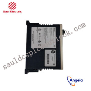
Description
- BENTLY 3500/40M-01-00 gateway is designed with multi protocol compatibility and modularity, seamlessly connecting industrial systems,
- operating at a wide temperature range of -40 ° C to 85 ° C, supporting 8-channel rotating equipment monitoring,
- remote configuration to improve efficiency, and ensuring stable power and automation.
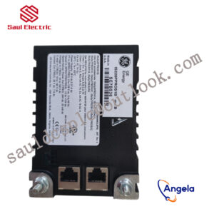
It can connect the Bently Nevada 3500 system with other control systems or host computers to achieve data interconnectivity.
thus achieving integration with other industrial control systems.
5 Fieldbus network layer5.1 mfb (master field bus) busThe mfb bus is a field LAN bus and is connected between mp200, mp90, s400i/o, OPC (small control station) and the transmission system. The mfb communication bus uses coaxial cables and twisted pairs. It connects the ci520/ci525/ci526 communication interface module and the dstc452 modem. The ends of each twisted pair must be isolated, and the shielding layer of one end must be grounded. The communication of mfb The rate is 375kb/s, its resistance is 75 ohms, and its hardware configuration is shown in Figure 3. The relevant system information of mfb is obtained from the engineering station. The general order is time, information model, code, task number, sequence number, and data. It mainly displays the following states.Code 20: cpu communication interface contact lostCode 21: fatal hardware failureCode 39: device/staTIon okCode 72: device/statIon address okCode 120: Process failureCode-1: Execution errorCode -4: System errorCode -5: Minor system site errorCode-6: Communication failureCode-9: Catastrophic bus failureCode -10: Redundant cable interrupted5.2 af100 (advant field)/mb90 (master bus) busThe purpose of AF100/MB90 is to provide communication between multiple APC sites or between APC sites and ABB industrial system equipment. MB90 supports two different types of communication, data processing and information sending. The data set is dynamic data. Use To monitor and control a certain processing process, this process uses service information for parameterization, program installation, and diagnosis. AF100/MB90 is a high-performance regional bus capable of connecting up to 79 APC sites. The mb90 has a maximum length of 300 meters, and if equipped with appropriate signal cables and signal repeaters, and long-distance configurations between individual transmission devices are available, up to 2000 meters. Technical characteristics of the bus(1) Communication rate 1.5mbit/s(2) Attenuation bus length <300m, proliferation delay <2000m(3) Telegram length 2, 4, 6, 8,…32 bytes of user data.(4) Identification code (telegraph code) range 1…4000(5) Cycle time 2, 4, 8, 16, 32, 64, 128…2048 or 4096msaf100/mb90 relies on a centralized bus manager. The bus manager functions are relatively complex and have many requirements. For example, apc sites cannot be used as bus managers because they do not contain bus manager functions. To make communication between APCs via AF100/MB90 possible, each solution (standalone and embedded) can be used to arrange the bus master of AF100/MB90. When the APCs start executing their applications, the bus master must be operable, otherwise the data set function block within the apc branch will enter an error state when the locally configured data set is not acknowledged by the bus manager within the specified time limit. , if the system has only apc site and no masterpiece is connected to mb90 or ac450 and af100, an independent bus manager should be installed.The communication between ABB DCS and the transmission system (such as acv700/dcv700) is realized by relying on the drrtra (drive trans mi t) element and drrec (drive reciver) element shown in Figure 4 .The drrtra (drive transmit) element is used to pass a given data set to the abb drive controller and select the control word and command word signal of the drive signal. The definition of the control word and command word signal is given in the application drive software description. The drrtr element can generate different types of periodic messages supported by the drive communication protocol. The destination of the signal is selected by the drive signal. The drrtr element can also write parameters. In the normal phase, the overload of drrtr can be detected.The drrec (drive reciver) element is used to receive signals and control word values from the abb drive controller. The definitions of these signals are given in the application drive software description. The drrec element is just periodic information supported by the drive connection protocol. The receiving data source is selected by determining the drive signal and signal index through the element input parameters. The drrec element also has access to parameters, and overloads of drrec can be detected during configuration.
19000-00-90-18-02 3500 series front card and rear card
3500/42M 140734-99 Bently State Monitoring Interface System
3500/33-1-00 Mechanical vibration monitoring system
3500/93 135785-01 BENTLY series: 3500 communication gateway module
149369-01 Belonging to the Bently Nevada 3500 series
3500/34 125696-01 3500 series front card and rear card
3500/42M-04-CN BENTLY series: 3500 communication gateway module
330704-000-040-10-02-00 Bently State Monitoring Interface System
3500/40M ( 140734-01 ) Bently State Monitoring Interface System
3300/15 Bently State Monitoring Interface System
3500/22M BENTLY TSI system module
3500/62-04-00 BENTLY series: 3500 communication gateway module
3500-92-02-01-00 Mechanical vibration monitoring system
3500/54M Bently State Monitoring Interface System
3500/05-01-02-00-00-00 BENTLY series: 3500 communication gateway module
106M1081-01 Mechanical vibration monitoring system
3500/42M 176449-02 Mechanical vibration monitoring system
3500/15 106M1081-01 BENTLY TSI system module
3500/53-03-00 3500 series front card and rear card
3300/61 3500 series front card and rear card