Description
IS210MACCH1AKH Product Introduction
The specific application scope of the product
will depend on the needs of system integration and industrial application, but generally speaking, this type of embedded controller module can be applied to the following categories:
manufacturing processes, etc.
monitoring and control system.
of the controller module, as well as the specific needs of the customer.
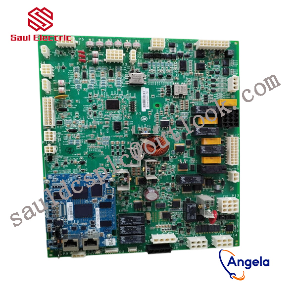
designed to manage gas or steam turbines.
It has a CIMPLICITY graphical interface and an HMI with software suitable for running heavy-duty turbines.
be installed at the bottom of the cabinet. For a small setup that is easy to serve a triple redundant system, up to three components can be installed side by side.
he board can operate within a temperature range of 0 to 65 degrees Celsius without the need for a fan for cooling. NFPA Class 1. This board can be used for two applications.
Figure 4 Tool Framework2.3Smart component creationCall the Rotator component: This component is used to allow the rotatable grinding rotor to rotate during simulation to simulate the real grinding scene. In the parameters of the Rotator component, set the reference to object, the reference object to the frame l, and the object to a copy of the rotor. (2) The rotary grinding rotor can be rotated, and the speed is l20mm/s (the speed of the grinding head will affect the quality of the finished product) ), the reference center axis is: axis (based on frame l, centerpoint x, y,: set to 0, 0, 0, Axis set x, y,: 0, 0, l000mm).Call the Attach component: This component is used to allow the rotatable grinding rotor to be integrated with the tool body. When the tool body is installed on the flange, it can follow the movement of the flange. In the parameters of the Attach component, set the sub-object to be a copy of the rotor (2) for the rotatable polishing rotor, and the parent object is the tool body of a copy of the rotor. The offset and orientation are based on the offset of point B relative to the origin. For setting, you can use the measurement tool in Robotstudio software to measure, and then set the parameters after measurement.Verification: Install a copy of the rotor tool body onto the robot flange, and then click Execute in the Attach component. You can observe whether the position of the rotatable grinding rotor is correct at this time. If there is a deviation, adjust the position in time, as shown in the figure. 5 shown.Figure 5 Tool installation2.4 Create tool coordinate systemUse the six-point method to create the tool coordinate system Too1data on the robot teach pendant at the center of the rotor. Change the tool coordinate system to Too1data in the basic options. At this time, click on the robot manual linear and you can drag the robot to move linearly at will.2.5 Creating trajectories and programmingDetermine the trajectory: According to the requirements of the work task, design the grinding trajectory around the workpiece and determine the trajectory points and transition points required for the grinding trajectory. The grinding action process is shown in Figure 6.Setting I/O and programming: Yalong IY-l3-LA industrial robot deburring and grinding system control and application equipment adopts 0sDC-52 6/o communication board, the address is 10, Do1 is the digital output signal, the address is 1 . First set the I/O board, then set the I/O digital output signal Di1, and then program on the simulation teaching pendant. The procedure is as follows:PRoCmain()setDo1: Set the Do1 signal to allow the external grinding rotor to start rotating.waitTime1: The robot stays in place and does not move, waits for 1s, and lets the polishing rotor turn to the specified speed, transitionMoveAbsjjpos10NoEoffs,v1000,z50,Too1data1: The robot moves to the initial point jpos10 above point p10. Point jpos10 is used as the starting point and end point of the robot”s action.Move4p10,v1000,z50,Too1data1: Move straight line grinding to point p10Move4pL0,v1000,z50,Too1data1: Move straight line grinding to pL0 pointMove4p30,v1000,z50,Too1data1: Move straight line grinding to point p30Move4p40,v1000,z50,Too1data1: Move straight line grinding to p40 pointMove4p10,v1000,z50,Too1data1: Move straight line grinding to point p10MoveAbsjjpos10NoEoffs,v1000,z50,Too1data1: The robot moves to the initial point jpos10 above point p10waitTime1: wait 1s, transitionResetDo1: Reset the Do1 signal to stop the rotor ENDPRoC2.6 Simulation design and verificationSimulation design: Create a smart component to input the Di1 signal, and use the Di1 signal to simulate the external polishing start signal to execute the Rotator component and Attach component of the smart component to achieve the visual effect of rotating and polishing the polishing rotor. In the workstation logic design, the smart component input Di1 signal is associated with the robot Do1 signal, so that the robot signal Do1 can control the smart component input Di1 signal, thereby controlling the start and stop of the rotation of the polishing rotor.Verification: In the program of the teaching pendant, first set the pp command to move to Main, and then set the robot startup mode to automatic. Click play in the simulation of Robotstudio software to verify whether the trajectory is consistent with the assumption, and optimize the path in time for problems existing in the simulation.3Summary and outlookThis design is based on the programming simulation of the Yalong Y4-1360A industrial robot deburring system to control the grinding robot workstation. It covers aspects such as creating a workstation, setting up tools, creating smart components, creating tool coordinate systems, creating trajectories, programming, simulation design, and verification. Starting with it, the polishing simulation of the workstation is realized through the smart component function of Robotstudio software. The animation effect is intuitive and lifelike, which not only facilitates teaching demonstrations, but also facilitates program debugging, and has application value for both production and teaching.In the planning and design of the workpiece grinding trajectory, according to the different roughness and grinding amount process requirements of the workpiece, the rotation speed, feed speed, feed amount, and grinding angle of the grinding rotor are also different. The feed amount can be adjusted in time according to the on-site conditions. , feed speed, rotor speed, grinding angle and other parameters. After appropriate adjustments, the motion trajectory is written with the corresponding program on the Robotstudio software to further reduce the possibility of robot collisions and singular points contained in the trajectory during the actual debugging process. ,Optimize paths and improve debugging efficiency.
DS200TCQAG1A High performance processor module GE
IS2020RKPSG From General Electric in the United States
IS215WEPAH2BA Gas turbine system Mark VI
IS210AEBIH1B From General Electric in the United States
IS400TCASH1AEC GE power control board
IS220PPRFH1A Gas turbine system Mark VI
IS200RCSAG1ABB Gas turbine system Mark VI
IS200JPDMG1A Gas turbine system Mark VI
DS2020FEXAG4 GE power control board
IS410TRLYS2F Processor/Controller Mark VI System
IS200ERIOH1ACB GE power control board
DS200DSPCH1ADA GE power control board
IS215UCCAM03A I/O excitation redundant module GE
IS230STCIH6A Gas turbine system Mark VI
IS200EPCTG1A From General Electric in the United States
IS200TTPWH1A I/O excitation redundant module GE
IS200SSCAH2AGD High performance processor module GE
DS200RTBAG2AGL High performance processor module GE
IS220PDIOH1B GE power control board
IS200TVIBH2BCC GE power control board
IS200ICIAH1ABB Processor/Controller Mark VI System
IS200EISBH1A GE power control board
IS400AEBMH1AJD Gas turbine system Mark VI
IS200TDBSH2AAA Gas turbine system Mark VI
IS215UCVEH2AB From General Electric in the United States
DS200KLDBG1ABC Gas turbine system Mark VI
IS200TSVCH2AED Gas turbine system Mark VI
IS210AEBIH1BED Processor/Controller Mark VI System
IS230STAIH2A Processor/Controller Mark VI System
DS200SLCCG3A Processor/Controller Mark VI System
DS200FCGDH1BBA High performance processor module GE
DS200RTBAG3A From General Electric in the United States
IS200TNH1A From General Electric in the United States
IS200DSPXH1DBD From General Electric in the United States
IS220PVIBH1A Processor/Controller Mark VI System
IS200STCIH2A From General Electric in the United States
IS420UCSBH4A I/O excitation redundant module GE
IS215UCVEM09A I/O excitation redundant module GE
IS420USBH1A From General Electric in the United States
IS200EPDMG1ABA Gas turbine system Mark VI
IS215VCMIH2CC Processor/Controller Mark VI System
IS200ERIOH1AAA I/O excitation redundant module GE
DS200QTBAG1ADC Gas turbine system Mark VI
IS200EAUXH1A High performance processor module GE
IS210AEDBH4A Gas turbine system Mark VI
IS215VPROH1BD From General Electric in the United States
IS200ACLEH1A From General Electric in the United States
IS200TBA1H1C GE power control board
DS3800HRCA1D1B GE power control board
IS200TVBAH2ACC Processor/Controller Mark VI System
DS3800HFXA1D1B High performance processor module GE
IS415UCVGH1A Gas turbine system Mark VI
IS410JPDHG1A Gas turbine system Mark VI
IS400WPDFH1A From General Electric in the United States
IS220PDIOH1B Gas turbine system Mark VI
IS200BPIHH1A High performance processor module GE
DS200TCEBG1ACD GE power control board
DS3800DFXA1B1C From General Electric in the United States
IS210AEBIH3BED I/O excitation redundant module GE
IS200TRTDH1B Gas turbine system Mark VI
IS215PCMIH1A High performance processor module GE
IS220PPRFH1B Gas turbine system Mark VI
IS420UCECH1B High performance processor module GE
DS200FCRRG1A From General Electric in the United States
DS200SDCCG1AHD I/O excitation redundant module GE
IS210MVRAH2A Gas turbine system Mark VI
IS200EXHSG1A GE power control board
IS220PHRAH1BD GE power control board
IS200IGPAG2AED From General Electric in the United States