Description
9907-827 Controller debugger generator WOODWARD
Non differential regulation is mainly used for constant speed control and is suitable for single machine operation or multiple prime movers working together in an isolated power grid. Differential regulation provides more control flexibility.
further enhancing its performance and application range.
rich additional functions, and high-precision output signals. Whether it is in the fields of generator sets, compressors, pump stations, or ships and locomotives, it can effectively ensure the stable operation of equipment within the set range.
power measurement level 1, editable screen, multi interface toolkit connection, etc. All details can be found in Woodward easyYgen manual 37582A
The rated operating temperature range of this model is -20 to 70 ° C; the rated temperature range of the LT model is -40 to 70 ° C, suitable for outdoor use.
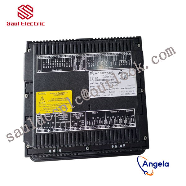
9907-827 is equipped with a monitor (not available on the 3100 model) and is designed for front panel installation.
The built-in HMI has a color LCD and soft keys (now with dedicated buttons) for direct control of the 9907-827 device. Multi level password protection can prevent unauthorized changes.
The generator set has four operating modes and the option to configure a manual circuit breaker control device.
How to use 9907-827?
What is 9907-827 used for?
9907-827 Customs Code
Figure 4 Tool Framework2.3Smart component creationCall the Rotator component: This component is used to allow the rotatable grinding rotor to rotate during simulation to simulate the real grinding scene. In the parameters of the Rotator component, set the reference to object, the reference object to the frame l, and the object to a copy of the rotor. (2) The rotary grinding rotor can be rotated, and the speed is l20mm/s (the speed of the grinding head will affect the quality of the finished product) ), the reference center axis is: axis (based on frame l, centerpoint x, y,: set to 0, 0, 0, Axis set x, y,: 0, 0, l000mm).Call the Attach component: This component is used to allow the rotatable grinding rotor to be integrated with the tool body. When the tool body is installed on the flange, it can follow the movement of the flange. In the parameters of the Attach component, set the sub-object to be a copy of the rotor (2) for the rotatable polishing rotor, and the parent object is the tool body of a copy of the rotor. The offset and orientation are based on the offset of point B relative to the origin. For setting, you can use the measurement tool in Robotstudio software to measure, and then set the parameters after measurement.Verification: Install a copy of the rotor tool body onto the robot flange, and then click Execute in the Attach component. You can observe whether the position of the rotatable grinding rotor is correct at this time. If there is a deviation, adjust the position in time, as shown in the figure. 5 shown.Figure 5 Tool installation2.4 Create tool coordinate systemUse the six-point method to create the tool coordinate system Too1data on the robot teach pendant at the center of the rotor. Change the tool coordinate system to Too1data in the basic options. At this time, click on the robot manual linear and you can drag the robot to move linearly at will.2.5 Creating trajectories and programmingDetermine the trajectory: According to the requirements of the work task, design the grinding trajectory around the workpiece and determine the trajectory points and transition points required for the grinding trajectory. The grinding action process is shown in Figure 6.Setting I/O and programming: Yalong IY-l3-LA industrial robot deburring and grinding system control and application equipment adopts 0sDC-52 6/o communication board, the address is 10, Do1 is the digital output signal, the address is 1 . First set the I/O board, then set the I/O digital output signal Di1, and then program on the simulation teaching pendant. The procedure is as follows:PRoCmain()setDo1: Set the Do1 signal to allow the external grinding rotor to start rotating.waitTime1: The robot stays in place and does not move, waits for 1s, and lets the polishing rotor turn to the specified speed, transitionMoveAbsjjpos10NoEoffs,v1000,z50,Too1data1: The robot moves to the initial point jpos10 above point p10. Point jpos10 is used as the starting point and end point of the robot”s action.Move4p10,v1000,z50,Too1data1: Move straight line grinding to point p10Move4pL0,v1000,z50,Too1data1: Move straight line grinding to pL0 pointMove4p30,v1000,z50,Too1data1: Move straight line grinding to point p30Move4p40,v1000,z50,Too1data1: Move straight line grinding to p40 pointMove4p10,v1000,z50,Too1data1: Move straight line grinding to point p10MoveAbsjjpos10NoEoffs,v1000,z50,Too1data1: The robot moves to the initial point jpos10 above point p10waitTime1: wait 1s, transitionResetDo1: Reset the Do1 signal to stop the rotor ENDPRoC2.6 Simulation design and verificationSimulation design: Create a smart component to input the Di1 signal, and use the Di1 signal to simulate the external polishing start signal to execute the Rotator component and Attach component of the smart component to achieve the visual effect of rotating and polishing the polishing rotor. In the workstation logic design, the smart component input Di1 signal is associated with the robot Do1 signal, so that the robot signal Do1 can control the smart component input Di1 signal, thereby controlling the start and stop of the rotation of the polishing rotor.Verification: In the program of the teaching pendant, first set the pp command to move to Main, and then set the robot startup mode to automatic. Click play in the simulation of Robotstudio software to verify whether the trajectory is consistent with the assumption, and optimize the path in time for problems existing in the simulation.3Summary and outlookThis design is based on the programming simulation of the Yalong Y4-1360A industrial robot deburring system to control the grinding robot workstation. It covers aspects such as creating a workstation, setting up tools, creating smart components, creating tool coordinate systems, creating trajectories, programming, simulation design, and verification. Starting with it, the polishing simulation of the workstation is realized through the smart component function of Robotstudio software. The animation effect is intuitive and lifelike, which not only facilitates teaching demonstrations, but also facilitates program debugging, and has application value for both production and teaching.In the planning and design of the workpiece grinding trajectory, according to the different roughness and grinding amount process requirements of the workpiece, the rotation speed, feed speed, feed amount, and grinding angle of the grinding rotor are also different. The feed amount can be adjusted in time according to the on-site conditions. , feed speed, rotor speed, grinding angle and other parameters. After appropriate adjustments, the motion trajectory is written with the corresponding program on the Robotstudio software to further reduce the possibility of robot collisions and singular points contained in the trajectory during the actual debugging process. ,Optimize paths and improve debugging efficiency.
8273-041 WOODWARD Speed Sensor Full Series
8272-781A Generator Parts Speed Controller 2301A Speed
5464-541 Generator Parts Speed Controller 2301A Speed
9904-111 Controller debugger generator WOODWARD
5463-405 WOODWARD Speed Sensor Full Series
8226-043 WOODWARD Speed Sensor Full Series
9904-254 WOODWARD 2301A Speed Control Controller
9907-162 WOODWARD Speed Sensor Full Series
9907-252 Generator Parts Speed Controller 2301A Speed
31902-02 WOODWARD Speed Sensor Full Series
5430-856 WOODWARD generator set speed control board
9907-1200 WOODWARD generator set speed control board
8273-140 Generator Parts Speed Controller 2301A Speed
8915-861 Controller debugger generator WOODWARD
5463-581 WOODWARD 2301A Speed Control Controller
5464-655 Generator Parts Speed Controller 2301A Speed
8580-069 Controller debugger generator WOODWARD
5437-465 Controller debugger generator WOODWARD
UG-10D WOODWARD 2301A Speed Control Controller
5462-750 From Woodward, USA
5441-691 Controller debugger generator WOODWARD
8271-674 From Woodward, USA
5439-800 WOODWARD 2301A Speed Control Controller
9907-120 From Woodward, USA
5466-031 WOODWARD generator set speed control board
5461-650 Generator Parts Speed Controller 2301A Speed
8200-1302 Controller debugger generator WOODWARD
5463-120 WOODWARD Speed Sensor Full Series
5464-223 WOODWARD generator set speed control board
5461-773 WOODWARD 2301A Speed Control Controller
5461-651 From Woodward, USA
9907-1290 From Woodward, USA
5462-532 Controller debugger generator WOODWARD
5466-259 Controller debugger generator WOODWARD