Description
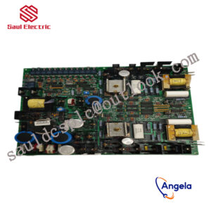
8250-807 Controller debugger generator WOODWARD
Non differential regulation is mainly used for constant speed control and is suitable for single machine operation or multiple prime movers working together in an isolated power grid. Differential regulation provides more control flexibility.
further enhancing its performance and application range.
rich additional functions, and high-precision output signals. Whether it is in the fields of generator sets, compressors, pump stations, or ships and locomotives, it can effectively ensure the stable operation of equipment within the set range.
power measurement level 1, editable screen, multi interface toolkit connection, etc. All details can be found in Woodward easyYgen manual 37582A
The rated operating temperature range of this model is -20 to 70 ° C; the rated temperature range of the LT model is -40 to 70 ° C, suitable for outdoor use.
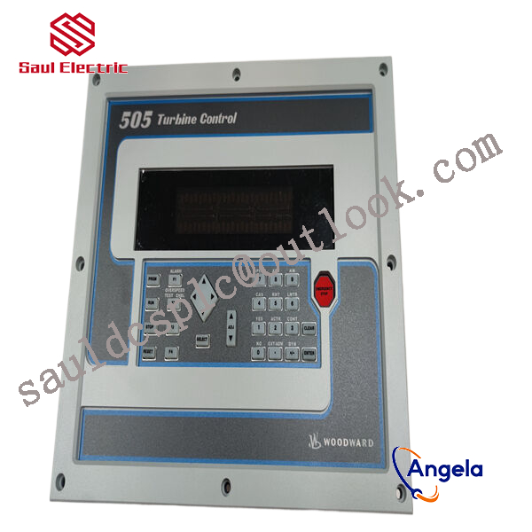
8250-807 is equipped with a monitor (not available on the 3100 model) and is designed for front panel installation.
The built-in HMI has a color LCD and soft keys (now with dedicated buttons) for direct control of the 8250-807 device. Multi level password protection can prevent unauthorized changes.
The generator set has four operating modes and the option to configure a manual circuit breaker control device.
How to use 8250-807?
What is 8250-807 used for?
8250-807 Customs Code
Practical application of ABB industrial information control system 800xA in main shaft hoist controlintroductionThe mine hoist is an important transportation equipment for mining enterprises. Its main function is to transport the ore, personnel or equipment that need to be transported to the destination by the lifting container. Therefore, it plays a very important role in the mining production process. Usually the mine hoist control system consists of a driving part and a control part. The working mechanism of the driving part is: the motor unit drives the mechanical hoisting device, and the frequency converter or other types of hoisting control systems drive the motor unit: the working mechanism of the control part is: Each component of the hoist is coordinated and controlled by the Distributed Control System (DCS). In addition to completing basic process control, it can also integrate intelligent instruments, intelligent transmission and motor control, and even production management and safety systems into one operation and engineering environment. middle. Therefore, the mine hoist requires a control system with high performance, high reliability, and high integration.1ABB800xA system and AC800M controller introduction1.1ABB800xA system introductionThe 800xA system is an industrial information control system launched by ABB. The core of its architecture is object-oriented (ObjectOriented) technology. Due to the adoption of ABB”s unique Aspect0object concept, enterprise-level information access, object navigation and access can become standardized and simple.In order to provide a unified information platform for enterprise managers and technical personnel, the 800xA system provides a base platform (BasePlatform), which relatively separates the process control part and production control management and organically combines them together. As shown in Figure 1, the middle part is the basic platform, the upper part is the production control management part, and the lower part is the process control part. The basic platform provides standard interfaces for these two parts for data exchange.1.2 Introduction to ABBAC800M controller and its programming configuration toolsAC800M controller is ABB”s latest controller series, which includes a series of processors from PM851 to PM865. The AC800M controller itself has a pair of redundant TCP/IP interfaces. It can use the MMs protocol to communicate with other control devices and 800xA operator stations through Ethernet. It can also use the Modbus protocol and Point-Point protocol through 2 serial ports. communication. The programming and configuration tool of AC800M is ControlBuilderM, referred to as CBM. It supports standard ladder diagram, function block language, text description language and assembly language to write control logic.2. Improve the design and implementation of control system functions2.1 Implementation of elevator operating speed curveOne of the main tasks of the lifting control system is to control the lifting motor to operate according to the speed-position curve given by the design, so that the lifting container passes through the acceleration section, the uniform speed section and the deceleration section successively, and stops accurately after completing the specified lifting distance. somewhere in the wellbore. In order to realize the function of precise position calculation, the designed elevator control system must be able to perform high-precision position calculation based on the photoelectric encoder connected to the main shaft of the elevator drum. The calculation formula is as follows:In the formula, s is the actual position value of the elevator: sp is the distance corresponding to two consecutive encoder pulses: AN is the difference between the encoder count value at the reference position and the current position (signed variable): s0 is the reference position value.The encoder counts are distributed according to the circumference of the drum. After the number of pulses Np generated by the encoder rotation is known, the diameter of the circumference of the centerline of the wire rope wrapped around the drum must be accurately known, so that it can be calculated according to formula (2) The distance sp corresponding to the two encoder pulses:In the formula, D is the circumferential diameter of the centerline of the wire rope: Np is the number of pulses for one revolution of the known encoder.But in formula (2), there is a value D that keeps getting smaller as the system runs. This is because the wire rope used in the elevator is wrapped around the drum, and there is a lining between the wire rope and the drum that increases friction. This liner will become thinner and thinner as the system continues to wear and tear, causing the diameter of the circle formed by the center line of the steel wire rope to gradually become smaller. When the pad wears to a certain extent, it will cause a large position calculation error. In order to solve the above problems, the two parking position switches in the shaft are used to correct the drum diameter, because the distance between the two parking positions can be obtained through actual measurement with high accuracy. During the actual operation, record the encoder count values at the two parking positions respectively. According to formula (3), the actual correction value of sp can be calculated:In the formula, sd is the distance between two parking positions: Abs is the absolute value operation: N is the encoder count value when there are two parking positions.In this way, the initial sp value is first set according to the given design parameter value, and then the value is corrected according to the actual operating conditions, which can effectively ensure the accuracy of position calculation. At the same time, sp” can also be substituted into formula (2), and the D value can be obtained in turn, which can be used as a basis for judging whether the liner is seriously worn.After obtaining the elevator position value, the speed control curve can be calculated according to formula (4):
9904-173 From Woodward, USA
8904-289 Generator Parts Speed Controller 2301A Speed
9907-490 Generator Parts Speed Controller 2301A Speed
5501-467 WOODWARD Speed Sensor Full Series
8200-1301 WOODWARD Speed Sensor Full Series
9907-716 WOODWARD generator set speed control board
8440-2088 WOODWARD 2301A Speed Control Controller
9907-1200 Controller debugger generator WOODWARD
5501-428 Controller debugger generator WOODWARD
9907-028 From Woodward, USA
5441-671 From Woodward, USA
5501-470 Generator Parts Speed Controller 2301A Speed
5500-018 Controller debugger generator WOODWARD
8236-027 WOODWARD generator set speed control board
5453-203 From Woodward, USA
8200-177 WOODWARD 2301A Speed Control Controller
8280-071 From Woodward, USA
9907-018 WOODWARD generator set speed control board
9907-561 Controller debugger generator WOODWARD
8236-043 From Woodward, USA
5464-843 WOODWARD Speed Sensor Full Series
8250-807 From Woodward, USA
9907-124 WOODWARD 2301A Speed Control Controller
5466-258 Generator Parts Speed Controller 2301A Speed
5464-458 Controller debugger generator WOODWARD
5466-274 From Woodward, USA
9907-624 Controller debugger generator WOODWARD
5437-418 Controller debugger generator WOODWARD
5462-244 WOODWARD generator set speed control board
5462-530 Generator Parts Speed Controller 2301A Speed
5437-281 Controller debugger generator WOODWARD
5460-796 Controller debugger generator WOODWARD
5501-466 WOODWARD 2301A Speed Control Controller
8915-652 WOODWARD 2301A Speed Control Controller
5463-887 WOODWARD 2301A Speed Control Controller
8280-071 WOODWARD Speed Sensor Full Series
5466-017 WOODWARD Speed Sensor Full Series