Description
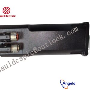
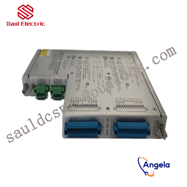
- BENTLY 3500/72M 140734-08 gateway is designed with multi protocol compatibility and modularity, seamlessly connecting industrial systems,
- operating at a wide temperature range of -40 ° C to 85 ° C, supporting 8-channel rotating equipment monitoring,
- remote configuration to improve efficiency, and ensuring stable power and automation.
It can connect the Bently Nevada 3500 system with other control systems or host computers to achieve data interconnectivity.
thus achieving integration with other industrial control systems.
Figure 4 Tool Framework2.3Smart component creationCall the Rotator component: This component is used to allow the rotatable grinding rotor to rotate during simulation to simulate the real grinding scene. In the parameters of the Rotator component, set the reference to object, the reference object to the frame l, and the object to a copy of the rotor. (2) The rotary grinding rotor can be rotated, and the speed is l20mm/s (the speed of the grinding head will affect the quality of the finished product) ), the reference center axis is: axis (based on frame l, centerpoint x, y,: set to 0, 0, 0, Axis set x, y,: 0, 0, l000mm).Call the Attach component: This component is used to allow the rotatable grinding rotor to be integrated with the tool body. When the tool body is installed on the flange, it can follow the movement of the flange. In the parameters of the Attach component, set the sub-object to be a copy of the rotor (2) for the rotatable polishing rotor, and the parent object is the tool body of a copy of the rotor. The offset and orientation are based on the offset of point B relative to the origin. For setting, you can use the measurement tool in Robotstudio software to measure, and then set the parameters after measurement.Verification: Install a copy of the rotor tool body onto the robot flange, and then click Execute in the Attach component. You can observe whether the position of the rotatable grinding rotor is correct at this time. If there is a deviation, adjust the position in time, as shown in the figure. 5 shown.Figure 5 Tool installation2.4 Create tool coordinate systemUse the six-point method to create the tool coordinate system Too1data on the robot teach pendant at the center of the rotor. Change the tool coordinate system to Too1data in the basic options. At this time, click on the robot manual linear and you can drag the robot to move linearly at will.2.5 Creating trajectories and programmingDetermine the trajectory: According to the requirements of the work task, design the grinding trajectory around the workpiece and determine the trajectory points and transition points required for the grinding trajectory. The grinding action process is shown in Figure 6.Setting I/O and programming: Yalong IY-l3-LA industrial robot deburring and grinding system control and application equipment adopts 0sDC-52 6/o communication board, the address is 10, Do1 is the digital output signal, the address is 1 . First set the I/O board, then set the I/O digital output signal Di1, and then program on the simulation teaching pendant. The procedure is as follows:PRoCmain()setDo1: Set the Do1 signal to allow the external grinding rotor to start rotating.waitTime1: The robot stays in place and does not move, waits for 1s, and lets the polishing rotor turn to the specified speed, transitionMoveAbsjjpos10NoEoffs,v1000,z50,Too1data1: The robot moves to the initial point jpos10 above point p10. Point jpos10 is used as the starting point and end point of the robot”s action.Move4p10,v1000,z50,Too1data1: Move straight line grinding to point p10Move4pL0,v1000,z50,Too1data1: Move straight line grinding to pL0 pointMove4p30,v1000,z50,Too1data1: Move straight line grinding to point p30Move4p40,v1000,z50,Too1data1: Move straight line grinding to p40 pointMove4p10,v1000,z50,Too1data1: Move straight line grinding to point p10MoveAbsjjpos10NoEoffs,v1000,z50,Too1data1: The robot moves to the initial point jpos10 above point p10waitTime1: wait 1s, transitionResetDo1: Reset the Do1 signal to stop the rotor ENDPRoC2.6 Simulation design and verificationSimulation design: Create a smart component to input the Di1 signal, and use the Di1 signal to simulate the external polishing start signal to execute the Rotator component and Attach component of the smart component to achieve the visual effect of rotating and polishing the polishing rotor. In the workstation logic design, the smart component input Di1 signal is associated with the robot Do1 signal, so that the robot signal Do1 can control the smart component input Di1 signal, thereby controlling the start and stop of the rotation of the polishing rotor.Verification: In the program of the teaching pendant, first set the pp command to move to Main, and then set the robot startup mode to automatic. Click play in the simulation of Robotstudio software to verify whether the trajectory is consistent with the assumption, and optimize the path in time for problems existing in the simulation.3Summary and outlookThis design is based on the programming simulation of the Yalong Y4-1360A industrial robot deburring system to control the grinding robot workstation. It covers aspects such as creating a workstation, setting up tools, creating smart components, creating tool coordinate systems, creating trajectories, programming, simulation design, and verification. Starting with it, the polishing simulation of the workstation is realized through the smart component function of Robotstudio software. The animation effect is intuitive and lifelike, which not only facilitates teaching demonstrations, but also facilitates program debugging, and has application value for both production and teaching.In the planning and design of the workpiece grinding trajectory, according to the different roughness and grinding amount process requirements of the workpiece, the rotation speed, feed speed, feed amount, and grinding angle of the grinding rotor are also different. The feed amount can be adjusted in time according to the on-site conditions. , feed speed, rotor speed, grinding angle and other parameters. After appropriate adjustments, the motion trajectory is written with the corresponding program on the Robotstudio software to further reduce the possibility of robot collisions and singular points contained in the trajectory during the actual debugging process. ,Optimize paths and improve debugging efficiency.
125388-01 BENTLY
125388-01H BENTLY
BENTLY 125680-01
125704-01 BENTLY
125720-01 BENTLY
125736-01 BENTLY
125760-01 BENTLY
125768-01 BENTLY
125800-01 BENTLY
125840-02 BENTLY
125840-01 BENTLY
128229-01 BENTLY
128275-01-E BENTLY
128276-011 BENTLY
129478-01 BENTLY
130944-01 BENTLY
132417-01 BENTLY
132419-01 BENTLY
133300-01 BENTLY
133396-01 BENTLY
133442-01 BENTLY
133819-01 BENTLY
133819-02 BENTLY
135462-01 BENTLY
BENTLY 135473-01
BENTLY 135489-01
BENTLY 135489-03
BENTLY 135489-04
BENTLY 135613-02
BENTLY 136188-01
BENTLY 136294-01
BENTLY 136711-01
BENTLY 136719-01
BENTLY 140471-01
BENTLY 146031-01
BENTLY 146031-02
BENTLY 149992-01
BENTLY 167699-02
BENTLY 1900/27-03-00
BENTLY 1900/55-0Z-01-01-01
BENTLY 1900/65A-01-01-01-00-00
BENTLY 1900/65A(167699-02)
BENTLY 1X35668 MADEEXCLUSIVELYBY
BENTLY 22810-01-05-50-02
BENTLY 2300/25-00
BENTLY 24765-02-01
BENTLY 3300/16-14-01-03-00-00-01
BENTLY 3300/20-12-01-03-00-00
BENTLY 330100-90-00