Description
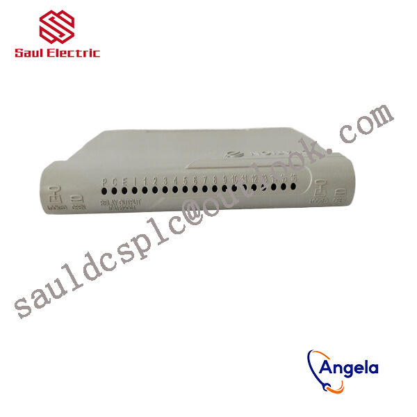
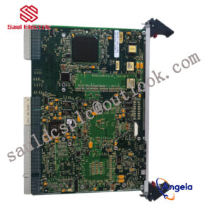
1X00163H01 Relay output logic module Emerson
thereby controlling external devices or circuits.
How to wire the BLDC driver
The wiring method of BLDC (brushless DC motor) drivers may vary depending on the specific driver model and usage scenario, but generally speaking, the wiring of BLDC drivers includes the following key parts:
1. Power wiring: BLDC drivers require external power supply. Usually, power wiring includes connecting the positive and negative poles of a DC power source (such as a battery) to the power input terminal of the driver.
2. Motor wiring: The BLDC driver names the three phase lines on the drive motor shaft as phase A, phase B, and phase C. Motor wiring generally includes connecting the A-phase, B-phase, and C-phase wires of the driver to the corresponding phase wires of the motor.
3. Sensor wiring (if any): Some BLDC drivers require the connection of sensors such as Hall sensors or encoders to obtain information on the motor’s rotational position and speed. Sensor wiring generally includes connecting the output signal line (usually three wires) of the sensor to the corresponding input terminal of the driver.
4. Control signal wiring: BLDC drivers typically require receiving control signals to control parameters such as motor speed and direction. The control signal wiring usually includes connecting the speed control, direction control, and enable pins of the driver to the corresponding output pins of the controller (such as microcontroller or PLC).
It should be noted that the wiring method of BLDC drivers is related to the specific driver model, and should refer to the selected driver’s manual or technical manual for correct wiring. In addition, it is recommended to ensure that the polarity and wiring of the power and signal lines are correct before wiring, and to follow the rated current and voltage requirements of the motor and driver to ensure safe and normal operation.
responsible for processing signals from on-site sensors or driving actuator actions. For example, they may need to cooperate with devices such
as BANNER travel switch T30UIPB to receive their transmitted position signals; Or by controlling components such as Burkert solenoid valve 00131421, the on/off of fluid media can be precisely managed.
these modules integrate more complex logic processing capabilities. The core task of a pressure switch is to detect whether the pressure
has reached a preset threshold and output a switch signal. Its function is highly specific and fixed. And modules 1X00163H01 and 1
C31219G01 have the ability to comprehensively judge multiple such switch signals and transmitter signals (such as transmitter 1066-P-HT-60),
and output complex control instructions according to internal logic.