Description
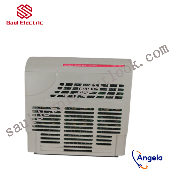
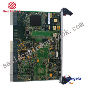
1X00163H01 Emerson redundant system output module
thereby controlling external devices or circuits.
1. Feedback logic of PID
The feedback logic terms of various frequency converters are different, and there are even cases where similar terms have opposite meanings. The system design should be based on the instruction manual of the selected frequency converter. The so-called feedback logic refers to the control polarity of the output frequency of the frequency converter based on the feedback signal detected by the sensor of the controlled physical quantity. For example, in the central air conditioning system, the return water temperature is used to control and regulate the output frequency of the frequency converter and the speed of the water pump motor. When heating in winter, if the return water temperature is low and the feedback signal decreases, it indicates that the room temperature is low. It is required to increase the output frequency of the frequency converter and the motor speed, and increase the flow rate of hot water; During summer cooling, if the return water temperature is too low and the feedback signal decreases, it indicates that the room temperature is too low. This can reduce the output frequency of the frequency converter and motor speed, and decrease the flow of cold water. As can be seen from the above, when the temperature is also low, the feedback signal decreases, but the frequency change direction of the frequency converter is required to be opposite. This is the reason for introducing feedback logic. The functional selection of several frequency converter feedback logics is shown in Table 1.
2. Enable PID function
To achieve closed-loop PID control function, the PID function should first be pre-set as valid. There are two specific methods: one is to preset the function parameter code of the frequency converter. For example, in the Convo CVF-G2 series frequency converter, when the parameter H-48 is set to O, there is no PID function; When set to 1, it is a normal PID control; When set to 2, it is the constant pressure water supply PID. The second is determined by the status of the external multifunctional terminals of the frequency converter. For example, in the Yaskawa CIMR-G 7A series frequency converter, as shown in Figure 1, select any one of the multifunctional input terminals Sl-S10 and preset the function codes H1-01 to H1-10 (corresponding to terminals S1-S10) to 19. This terminal has the function of determining whether PI [) control is effective. It is invalid when it is “ON” and effective when it is “OFF” with the common terminal SC. It should be noted that most frequency converters have both of the above preset methods, but there are a few brands of frequency converters that only have one of them.
In some systems with less strict control requirements, sometimes only using PI control function without activating D function can meet the needs, and the system debugging process is relatively simple.
responsible for processing signals from on-site sensors or driving actuator actions. For example, they may need to cooperate with devices such
as BANNER travel switch T30UIPB to receive their transmitted position signals; Or by controlling components such as Burkert solenoid valve 00131421, the on/off of fluid media can be precisely managed.
these modules integrate more complex logic processing capabilities. The core task of a pressure switch is to detect whether the pressure
has reached a preset threshold and output a switch signal. Its function is highly specific and fixed. And modules 1X00163H01 and 1
C31219G01 have the ability to comprehensively judge multiple such switch signals and transmitter signals (such as transmitter 1066-P-HT-60),
and output complex control instructions according to internal logic.