Description
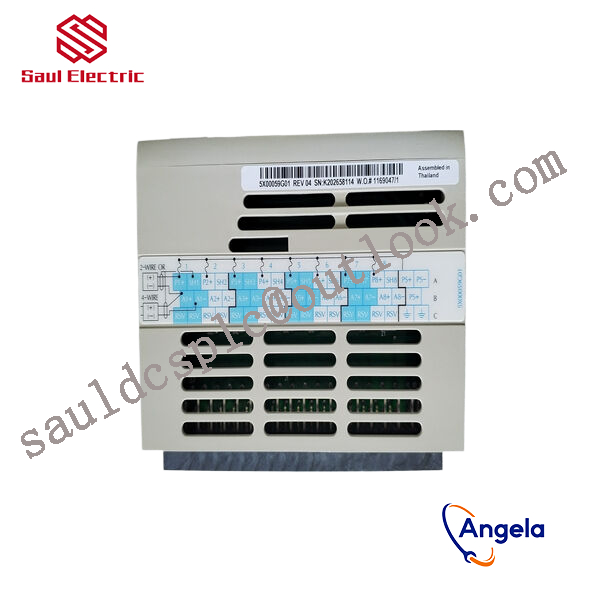
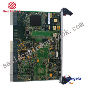
1C31232G02 Relay output logic module Emerson
thereby controlling external devices or circuits.

2. Take the → pointer as input and the ← pointer as output.
3. The meanings of each signal are as follows:
INH: Prohibit input of pulse commands (prohibited when open circuit);
OZ -: Z-phase output;
OZ+: Z-phase output;
S-RDY: The servo drive is ready;
ALM: Servo drive fault alarm;
COIN: Positioning completed;
SRV-ON: servo drive “on” signal;
COM -: Negative pole of power supply;
COM+: Positive pole of power supply;
PULS1: Command pulse input terminal;
PULS2: Command pulse input terminal;
SIGN1: Command pulse symbol input terminal;
SIGN2: Command pulse symbol input terminal;
Servo Drive Wiring Guide
In the field of industrial control automation, many devices have strict installation specifications. So, in order to avoid usage risks and eliminate safety hazards, what are the rules for connecting servo drives?
1. It is recommended to use a three-phase isolation transformer for power supply to reduce the possibility of electric shock.
2. It is recommended to use a noise filter for power supply to improve anti-interference ability.
3. Please install a non melting short-circuit circuit breaker to promptly cut off external power in case of driver failure.
4. The grounding wire should be ≥ 2.5m2, as thick as possible, and made into a single point grounding. The grounding terminal of the servo motor must be connected to the grounding terminal PE of the driver.
5. Connect the shielding layer of the cable correctly.
To prevent interference and misoperation, it is recommended to install a noise filter and pay attention to:
(1) The noise filter, servo drive, and upper controller should be installed as close as possible.
(2) Surge suppressors must be installed in relays, AC contactors, brakes, and other coils.
(3) Power circuit cables and signal lines should not be tied together.
responsible for processing signals from on-site sensors or driving actuator actions. For example, they may need to cooperate with devices such
as BANNER travel switch T30UIPB to receive their transmitted position signals; Or by controlling components such as Burkert solenoid valve 00131421, the on/off of fluid media can be precisely managed.
these modules integrate more complex logic processing capabilities. The core task of a pressure switch is to detect whether the pressure
has reached a preset threshold and output a switch signal. Its function is highly specific and fixed. And modules 1C31232G02 and 1
C31219G01 have the ability to comprehensively judge multiple such switch signals and transmitter signals (such as transmitter 1066-P-HT-60),
and output complex control instructions according to internal logic.