Description
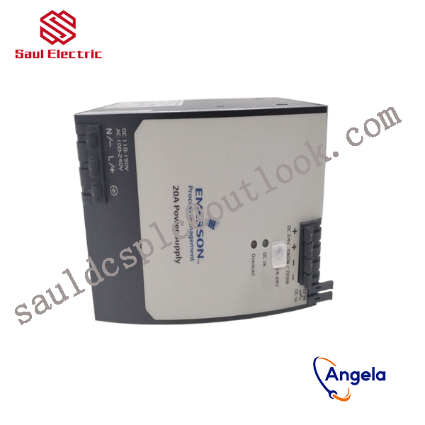
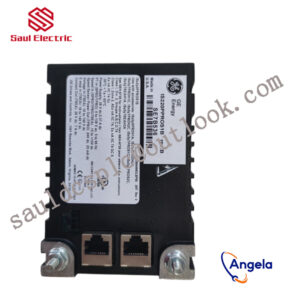
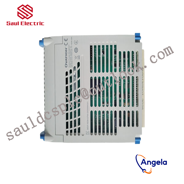
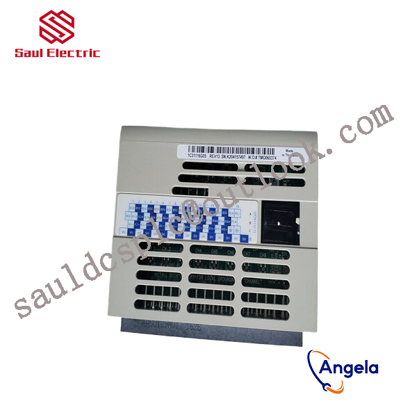
1C31166G02 Relay output logic module Emerson
thereby controlling external devices or circuits.
Input
The measured (controlled) value of the controlled object – PV, also known as process value; Usually comes from measuring units.
The set value of the controlled object – SP or SV, also known as the set value; Usually comes from the operating unit.
output:
The output value of the PID controller – CO, CV, or MV, also known as the PID output value; Generally output to handheld devices or output cards.
Parameter tuning of PID controller
The parameter tuning of PID controller is the core content of control system design. It determines the proportional coefficient, integration time, and differentiation time of the PID controller based on the characteristics of the controlled process. There are many methods for tuning PID controller parameters, which can be summarized into two categories: one is theoretical calculation tuning method. It mainly determines the controller parameters through theoretical calculations based on the mathematical model of the system. The calculation data obtained by this method may not be directly usable and must be adjusted and modified through engineering practice. The second is the engineering tuning method, which mainly relies on engineering experience and is directly carried out in the testing of control systems. The method is simple and easy to master, and is widely used in engineering practice. The engineering tuning methods for PID controller parameters mainly include critical ratio method, reaction curve method, and attenuation method. Each of the three methods has its own characteristics, and their commonality is to conduct experiments and then adjust the controller parameters according to engineering experience formulas. However, no matter which method is used, the controller parameters need to be finally adjusted and improved in actual operation. The commonly used method now is the critical ratio method. The steps for tuning PID controller parameters using this method are as follows: (1) Firstly, select a sufficiently short sampling period for the system to operate; (2) Only add a proportional control loop until the system exhibits critical oscillation in response to the step response of the input. Record the proportional amplification factor and critical oscillation period at this point; (3) Calculate the parameters of the PID controller through formulas under a certain degree of control.
responsible for processing signals from on-site sensors or driving actuator actions. For example, they may need to cooperate with devices such
as BANNER travel switch T30UIPB to receive their transmitted position signals; Or by controlling components such as Burkert solenoid valve 00131421, the on/off of fluid media can be precisely managed.
these modules integrate more complex logic processing capabilities. The core task of a pressure switch is to detect whether the pressure
has reached a preset threshold and output a switch signal. Its function is highly specific and fixed. And modules 1C31166G02 and 1
C31219G01 have the ability to comprehensively judge multiple such switch signals and transmitter signals (such as transmitter 1066-P-HT-60),
and output complex control instructions according to internal logic.