Description
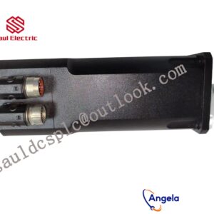
- BENTLY 128164-02-312-05-02-05 gateway is designed with multi protocol compatibility and modularity, seamlessly connecting industrial systems,
- operating at a wide temperature range of -40 ° C to 85 ° C, supporting 8-channel rotating equipment monitoring,
- remote configuration to improve efficiency, and ensuring stable power and automation.
It can connect the Bently Nevada 3500 system with other control systems or host computers to achieve data interconnectivity.
thus achieving integration with other industrial control systems.
Implementation of communication between ABC industrial robot and PLC based on DeviceNet fieldbus technologyintroductionIn modern production systems, industrial robots and PLCs need to communicate and collaborate to complete production tasks. That is, the industrial robots output signals to the PLC, allowing the PLC to control related equipment to drive the robot”s front-end tools. This article mainly analyzes the communication problems between ABB industrial robots and PLC based on DeviceNet fieldbus technology. DeviceNet is a common network communication method in the field of automation. ABB industrial robots establish a network to communicate with Siemens PLC based on the DeviceNet network.1Configure DSQC652There are mainly 5 types of standard I/0 boards commonly used in ABB industrial robots [2]. Except for the different addresses assigned to them during setup, their configuration methods are basically the same. This article mainly analyzes the ABB standard I/0 board DS0C652, which mainly builds communication modules based on the DeviceNet network. The DS0C652 board has a distributed I/O module with 16 digital input and 16 digital output interfaces. The board is installed in the ABB industrial robot control cabinet. First, define the specific operation steps of the DS0C652 board, enter the teach pendant control panel, then enter the configuration menu (Figure 1), select the DeviceNetDevice menu, and add a template to enter Figure 2. ABB standard I/0 board is hung on the DeviceNet network, so the address of the module in the network must be set. The jumpers 6 to 12 of terminal x5 are used to determine the address of the module. The available address range is 10 to 63. Modify the parameters in the template parameters to complete the DS0C652 board settings. Click the drop-down menu to select the “Use value from template” row, select “DS0C65224VDCI/0Device”, and then the parameters that need to be set include the address of the I/0 board in the bus.Figure 1 Configuring DSQC6522Configure signals and parametersAfter completing the DS0C652 board setting, the I/0 signal setting will be performed. Setting the I/0 signal is the basis for establishing communication with the PLC. The PLC communicates and transmits data with the ABB industrial robot through the I/0 signal and the DS0C652 board. As shown in Figure 3, in the signal configuration interface, there are many default I/0 points after the system is established. Modification is not allowed. Click “Add” to add signals. When setting input and output signals, their address range is 0~15. First, enter the signal menu in the configuration options to set the input and output types, and modify the corresponding parameters. After completing the settings, the computer prompts that you need to restart the settings. If there are multiple signals that need to be defined and the waiting time is long after restarting multiple times, you can click “Cancel” and wait for all signals to be defined before clicking the “Yes” button to restart. After the signal settings are completed, click to select “Input and Output” in the ABB menu to check whether all signals have been set.Figure 2 Configure DSQC652 parametersFigure 3 Signal parameter settingsDuring the signal establishment process, attention should be paid to the DSoC652 port and PLC port addresses used, and the corresponding address table should be established, as shown in Table 1. The robot interacts with the PLC through I/O signals. During the setting process, there must be no errors in the port and address number of the PLC connected to the DSoC652. If the address is set incorrectly, the communication between the robot and the PLC will not work properly.The entire robot teaching pendant setting process is shown in Figure 4.
128275-01 3500 series front card and rear card
3300/45 Bently State Monitoring Interface System
146031-01 3500 series front card and rear card
126632-01 Belonging to the Bently Nevada 3500 series
3500/25 149369-01 3500 series front card and rear card
3500/32 125712-01 Bently State Monitoring Interface System
ASSY78462-01U BENTLY series: 3500 communication gateway module
1900/65A 3500 series front card and rear card
3500/94 145988-01 Mechanical vibration monitoring system
125760-01 3500 series front card and rear card
3500/32M 149986-02 BENTLY TSI system module
330130-080-00-00 Mechanical vibration monitoring system
3500/42M 128229-01 BENTLY series: 3500 communication gateway module
3500/42M 176449-02 3500 series front card and rear card
125768-01 Mechanical vibration monitoring system
177992-01 Bently State Monitoring Interface System
3500/22M 3500 series front card and rear card
3500/32М 149986-02 BENTLY TSI system module
125736-01 BENTLY series: 3500 communication gateway module
3500/25-01-01-01 BENTLY TSI system module
330180-X1-05 BENTLY series: 3500 communication gateway module
3500/15 Belonging to the Bently Nevada 3500 series
3500/22M 288055-01 Mechanical vibration monitoring system
3500/92-02-01-00 Belonging to the Bently Nevada 3500 series
3500/22M BENTLY series: 3500 communication gateway module
3500/42M 3500 series front card and rear card
3500/33 BENTLY series: 3500 communication gateway module
81545-01 Bently State Monitoring Interface System
3500/22M 138607-02 Belonging to the Bently Nevada 3500 series
330500-02-04 BENTLY TSI system module
3500/40M 140734-01 BENTLY TSI system module
3500/40M 176449-01 Bently State Monitoring Interface System
3500/50 BENTLY TSI system module
135462-01 Bently State Monitoring Interface System
3500/72M 140734-08 BENTLY TSI system module
135489-01 BENTLY TSI system module
330180-50-00 BENTLY TSI system module
3500/22M 138607-01 3500 series front card and rear card
136294-01 3500 series front card and rear card
79492-01 Mechanical vibration monitoring system
135613-02 Bently State Monitoring Interface System
3500/50-01-01-00-00 3500 series front card and rear card
3500/65-01-00 Belonging to the Bently Nevada 3500 series
3500/50-04-00 Bently State Monitoring Interface System
3500/25 184684-01 BENTLY TSI system module
3500-53 Mechanical vibration monitoring system
3500/92-04-01-00 BENTLY series: 3500 communication gateway module
3500/70M 140734-09 BENTLY series: 3500 communication gateway module
3500/50M BENTLY TSI system module
3500/22 146031-02 Mechanical vibration monitoring system
3500/15 127610-01 Bently State Monitoring Interface System
24765-02-00 Mechanical vibration monitoring system
79492-01 BENTLY TSI system module